DJ Kurlander - Project Resources
Ray Tracing with Polarization
Overview
This research presents an approach for making computer generated images more realistic - particularly, how to make ray traced images more realistic by modeling the effects of polarization.
All light has a polarization state, and this constantly changes as the light bounces off of surfaces. Even completely unpolarized light becomes partially polarized as it reflects off of objects, and this polarization state profoundly affects how much light is reflected back. One of the key problems in computer generated imagery is accurately modeling how light bounces around a scene and eventually reaches the eye. Since polarization affects how much light is reflected off of each surface, we can generate more realistic pictures by tracking and taking into account its polarization state. Impossible you say? Read on!
How It Works
For the full details of our approach, read our paper on the topic, however here is a brief explanation of how things work. As with most ray tracers, we trace a ray of light through each pixel of the screen into the scene and see what it intersects. Unlike other ray tracers, each ray has a coherence matrix associated with it, which is a representation of the polarization state of light for that ray (as well as its intensity), and an additional vector perpendicular to the ray that indicates the coordinate system of the coherence matrix.
For each light source that is visible at this intersection point, we need to consider the specular contribution of that light source to this ray back to the eye. We use the Torrance-Sparrow lighting model (which is a physics-based lighting model commonly used in computer graphics that assumes the surface of an object is actually comprised of a distribution of microfacets) to determine the contribution from each light source. However, we incorporate polarization parameters into the Torrance-Sparrow model as described in detail in the paper. The light from each source has a coherence matrix associated with it, representing its polarization state. We use the formulas described in the paper to calculate its contribution to the ray from the intersection point back to the eye. Each contribution is itself in the form of a coherence matrix which needs to be transformed into the proper coordinate system to be summed.
As is typically the case with ray tracers, we recurse backwards to capture mirror reflections in the scene. These mirror reflections also contribute coherence matrices that contribute to the coherence matrix of the parent ray.
One important point is that the coherence matrix is really only valid for a given wavelength of light, so we simulate the color spectrum by performing these calculations at multiple wavelengths.
Examples
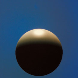
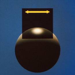
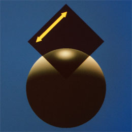
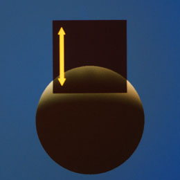
The panels above show images of light reflecting off of a sphere, with a polarizing filter in front of it. The first panel shows the sphere, which has a prominent specular highlight. Although the light was initially unpolarized, the angle of reflection is such that the specular reflection is entirely polarized in the X direction. Hence, the polarizing filter shown in the second panel, which transmits only light polarized in this X direction, transmits all of this specular highlight - but only half of the diffusely reflected light - creating greater contrast. As the polarizing filter is rotated 45 degrees and then 90 degrees in the last two panels, the specular highlight is first reduced and then eliminated entirely!
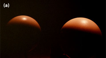
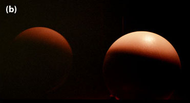
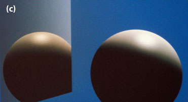

In this second example, we have four pictures above. Those in the top row are pictures of a real sphere being reflected in a mirror (in each case the mirror is positioned to the left of the sphere). In figure (a) we have a photograph of a real dielectric sphere being reflected in a metal mirror. In figure (b) we have a photograph of a real dielectric sphere being reflected in a dielectric mirror. Note that the metal mirror in (a) shows the specular highlight of the sphere, while the dielectric mirror in (b) does not. Due to the geometry of the scene, the specular highlight off of the dielectric mirror is totally eradicated, but reflections off of metal are less sensitive to polarization effects, so we still see the specular highlight in (a).
The bottom two computer generated images are both simulations of scene (b). In image (c) we use the traditional Torrance-Sparrow lighting model to simulate scene (b), but it incorrectly shows a specular highlight. In image (d) we use our enhanced lighting model with polarization, and here the specular highlight is totally eliminated - as it should be.
For additional examples, with more complex scenes (and prettier pictures!), please see the paper.
History
In 1987 Larry Wolff, a computer vision researcher with a strong background in the physics of light, asked David Kurlander about the possibility of incorporating polarization considerations in his ray tracing software. David was intrigued by the possibility, and using Larry's mathematical formulations, built the first computer graphics system that modeled polarization effects.